Translate This Page
Obviously, you can upgrade the battery bank on many Charger/Power Distribution units, but there are also some which have not been designed to handle the extra load of an upgraded battery bank.
There has been much said about the limits of a Motorhome Mains/230v Charger when battery banks are uprated, but what is rarely covered is the impact on the Alternator charging system and issues where factors other than the mains charger come into play.
What Effect Can Adding A Second Battery Have On Alternator Charging?
It is assumed that because the Alternator puts out 14.4v, it is that exact voltage that reaches the habitation area batteries. However, that is rarely the case.
Many of the motorhomes built in the UK have less than ideal alternator charging setups for the habitation batteries, very few show much above 13.9v at the habitation area batteries due to voltage drop in the cables, connectors and Power Controllers. This obviously results in slower Alternator to habitation battery charging.
Adding a second battery increases the load, often resulting in even greater voltage drop and a charge rate that is reduced even further.
When the set-up is optimum the Alternator charge rate at the habitation batteries should be close to the same Starter Battery 14.4v, even with two habitation area batteries.
Rather than just discuss this, we our going to document the workings of a real World 'Test case' we worked on to show how effective a typical motorhome actually is at charging the Habitation area battery from the Alternator and how it copes with additional loading.
We have selected a 2018 model Rapido with CBE equipment installed. The CBE installation usually performs better than the majority of British charge/controller systems, so a good demonstrator.
VEHICLE :
The customer had asked for a second AGM battery to be installed alongside the existing, awful Platinum AGMLB110L.
The vehicle has Solar which was charging the AGM habitation battery at a fixed 13.8v.
No provision for Solar charging of the Starter battery which was sitting at 12.9v.
START OF TEST.
With the Fridge off totally, and the battery in need of a charge, we started the engine.
START OF TEST.
With the Fridge off totally, and the battery in need of a charge, we started the engine.
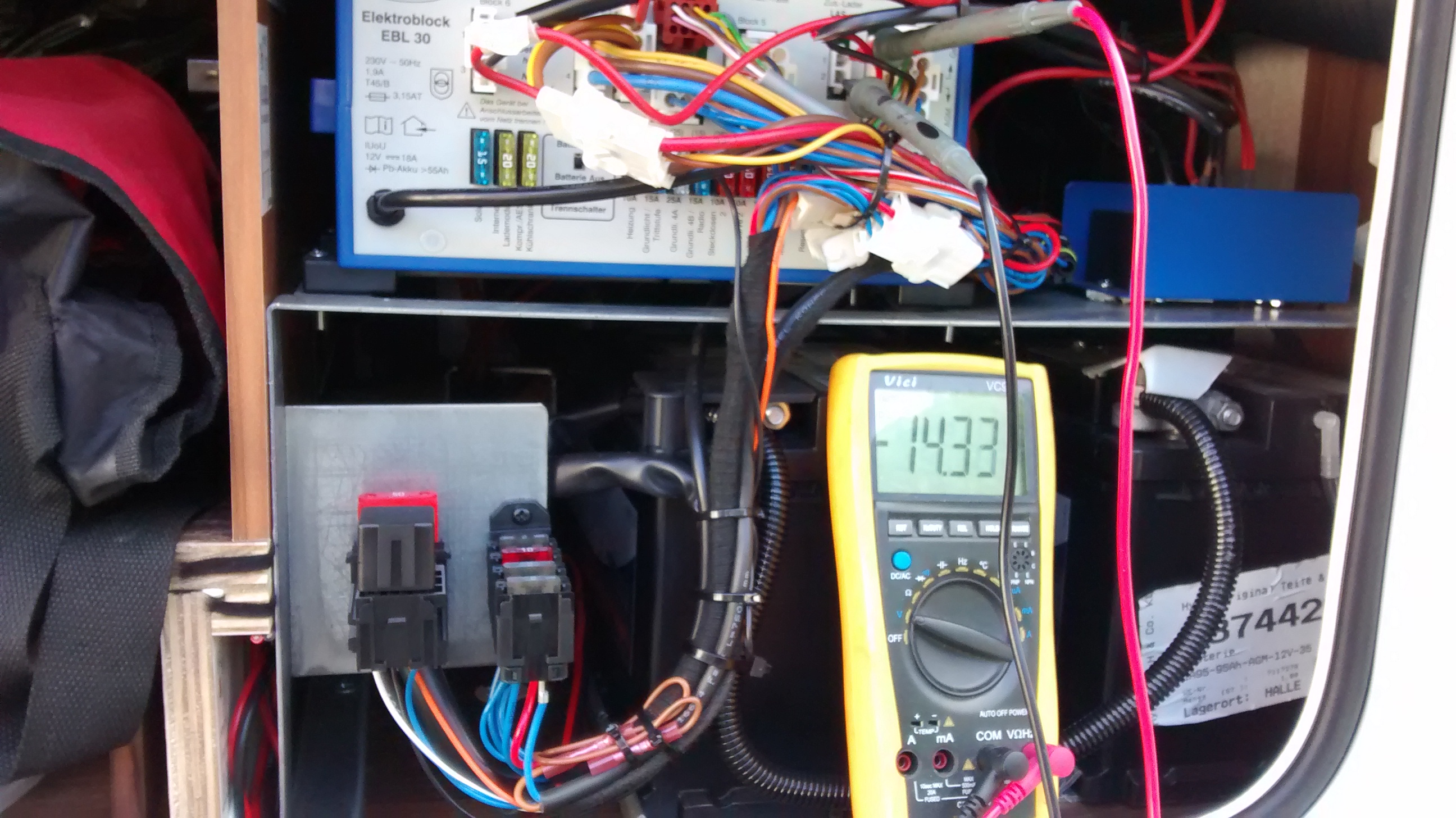
Starter battery charging went up to 14.4v confirming a good working Alternator and charge to the Starter battery.
The habitation battery voltage increased only very slightly to 13.9v not the 14.4v it should be.
We then activated the Fridge on 12v to create a 'normal driving' scenario and the load caused by the Fridge/Freezer resulted in the Starter Battery charge voltage dropping 0.2volts down to 14.2volts.
The charge at the habitation battery also dropped slightly to 13.8v.
13.8v is the exact same voltage used by mains chargers to 'trickle' charge a battery so it obviously isn't going to charge a battery very well at all.
You can see that by adding a second battery, the load will be even greater, resulting in further voltage drop and even slower charging.
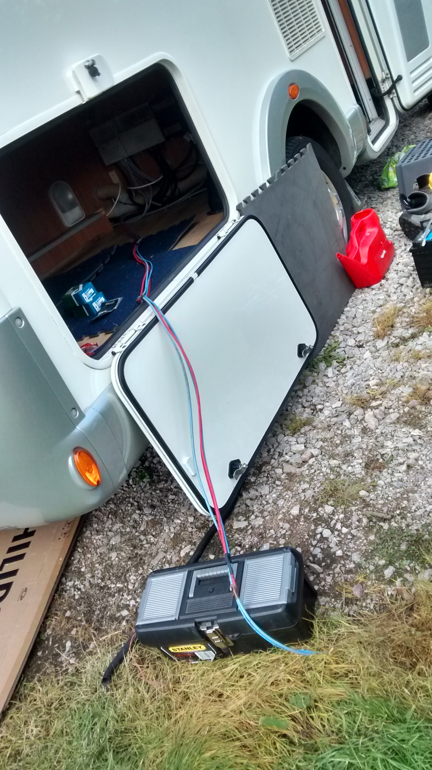
The CBE kit was installed ok, but the wiring/connectors were undersized and overlong.
The photo below shows that the Battery cable ran from the Starter battery at the front of the vehicle all the way to the back plus the equivalent of another metre or so further.
We moved the battery location further forward (reducing rear axle loading) taking about 4 metres out of the cable run.
These are typical 'real world' charging voltages at the habitation area batteries in a real travelling situation.
It is a test you can replicate on your own motorhome if you doubt us.
One motorhome owner, after having read our 'technicals' set out on his own test to prove us wrong.
He later wrote, "all I can say is... lesson learned and point taken Allan, the voltage was a miserable 13.7 - 13.9V".
You can see that at 13.9v, the Habitation area battery charge rate is a long, long way off the 14.7v that AGM batteries require and very different to the theoretical 14.4v the industry perceive takes place. That is only one of the reasons why AGM's just don't perform as motorhome habitation area batteries, they just are not at all tolerant of such a low charge rate.
Obviously if you Deep discharge a pair of habitation batteries down to 80% Depth Of Discharge, the higher load created may result in a voltage drop so great that the batteries may hardly charge at all.
That can result in the batteries taking a long time to charge and even not getting fully charged, 80% charged is not unusual.
Increasing the battery bank size doesn't always increase the battery Ah capacity to what you expect, unless you stay within the limits.
When adding a second battery check to see if you need to uprate the wiring from the Alternator, there is no need to fit a B2B, just as good results will come from making sure the wiring, connectors and Split charge relay are adequate.
See further down this page on how to supercharge your Alternator charging for less than £25, look for the section starting with a photo of a giant Black 'split charge' relay below.
Proof of how effective good design, cabling, connections and relay can be, are demonstrated by the photo below.
This is an image of a Hymer with a really well designed and installed Alternator charge set-up with two batteries. As can be seen the meter shows it is pretty close to 14.4v, just a 0.07v difference, and that is purely by sound design and installation -
This Hymer uses very short, high quality cable and minimal connectors to achieve a decent charge rate, even with two batteries, there are no voltage boost electronics involved.
This Hymer uses very short, high quality cable and minimal connectors to achieve a decent charge rate, even with two batteries, there are no voltage boost electronics involved.
This proves that the correct cabling, relay, etc. can deliver as good results as a B2B.
Most B2B installation instructions stipulate that the cabling must be upgraded by using very fat cabling as part of the install and it is this new big cable upgrade that achieves the bulk of the improvements, not the B2B electronic box itself.
If you only upgrade the cabling on a British motorhome, you will achieve just as good results without the huge cost or battery damaging impact of a Sterling B2B.
But that is not the only thing you need to consider, some power controller/charger units are not up to the task of supporting a second battery -
Motorhome Power Controllers/Chargers where the internal 230v Mains Charger itself is not the limit to the battery bank size.
Arsilicii
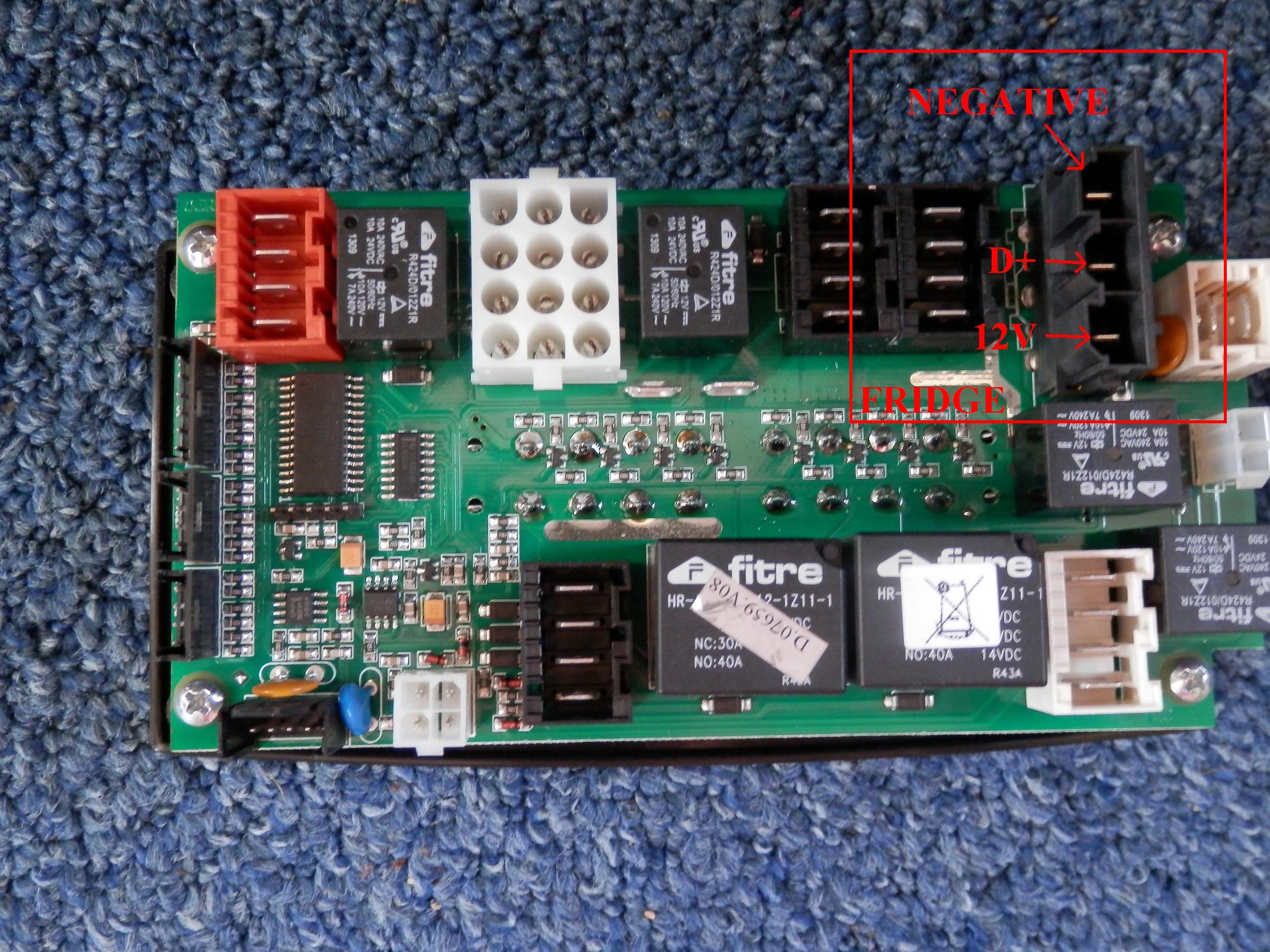
If you look at the Arsilicii 20amp Charger/Power Unit below you will note that the graphics on it's front show the Starter battery connects in through the Red, bottom left socket and the Habitation Battery through the top left, White socket.
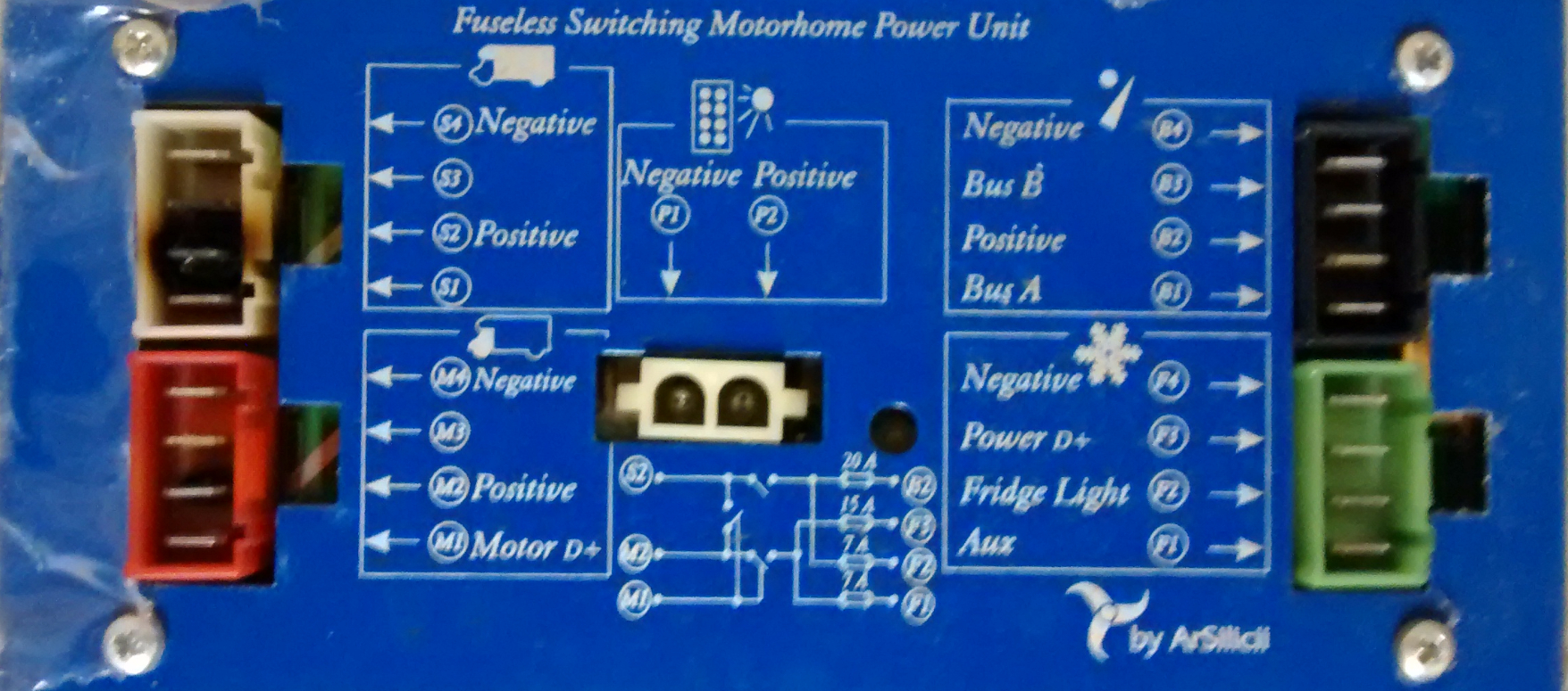
The box, like most continental built Power Units, has a built in Split Charge relay so that all current from the Alternator/Starter battery flows in through the Red Starter/Alternator connector, to the split charge relay and then out via the White Connector to the habitation battery.
Adding extra habitation batteries can result in up to 40amps of Alternator charge power going in through the Red and out of the White connectors.
The Fridge load, typically 17 amps for a Fridge/Freezer, additionally goes in the Red socket then out to the Fridge via the Green connector.
So the combined current passing in through a single Spade connector on the Red socket can be over 50amps if extra batteries are added.
The sockets on the later units have been uprated to higher power RAST5 versions, but even they will struggle if a second battery is added and allowed to become tired.
It can be seen in the photo above that both the Starter + and the Habitation battery + terminal are both overloaded and burnt, a very common issue where a second battery has been added.
Below is an early Arilicii Fuseboard with low power connectors :
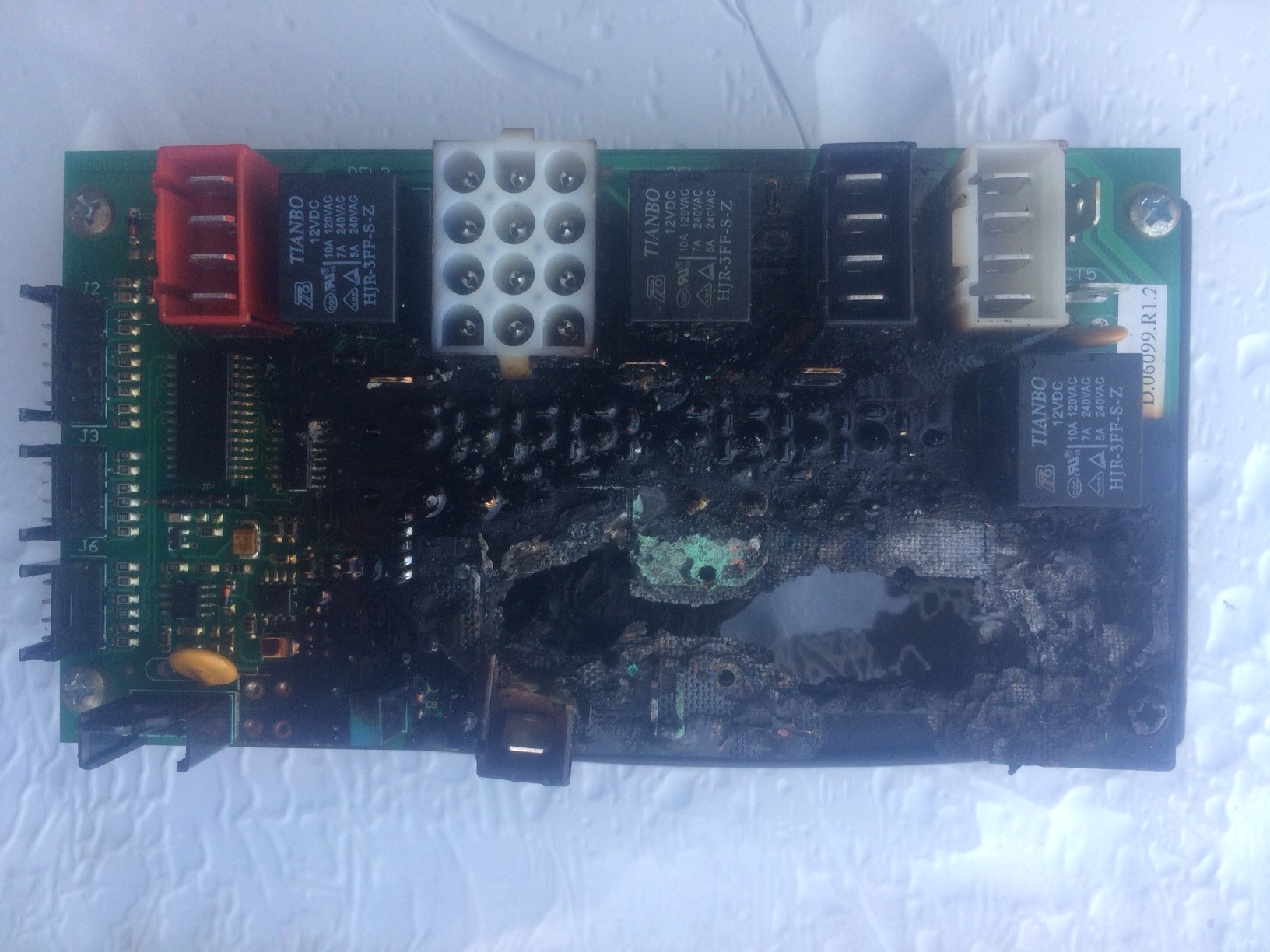
Something like this Fuseboard above is always too badly burnt to perform a meaningful post mortem, but you won't be surprised to learn that the centre of the fire is the Split charge relay with the Habitation battery sockets one side and the Starter Battery/Alternator feed the other.
If you upgrade to a Lithium battery, which can have 6 times the power loading of an ordinary battery, without appreciation of the systems and it's capability, then keep a very good Fire Extinguisher handy.
The burnt Fuseboard above should look similar to this new one below, although this is the latest version Fuseboard with uprated Rast5 connectors to better handle slightly higher current without burning.
Note the massively upgraded 12v Fridge connector, circled in Red, up from a 19amp rated socket to a 40amp socket, clearly these have also been a past issue? :
Although the connectors are uprated in later versions, they still won't cope with an overlarge battery bank.
Additionally the wiring remains the same which also isn't designed for heavy currents.
These fuseboards are not expected to pass currents that will even make them warm, let alone hot. As a result they tend to sit in enclosed boxes without ventilation. You can imagine how the the strain of running hot for short periods will place on the electronics leading to other issues, like overheating the of the IC's, etc.
So even the latest version, although more resistant to burning, will have issues with anything more than a single battery, UNLESS the discharge/recharge load is managed.
The above examples, and those below, clearly show the complications that can arise if you take a unit outside it's design. You can't just automatically add extra batteries to all Motorhomes without doing your homework.
Well you can, but there might be Tears.
This section is specifically aimed at the how the units cope with extra Alternator charge current when battery banks are enlarged. This is not about any limitations of Mains 230v chargers, that is documented on a separate page, HERE.
While we use a Arsilicii unit above to demonstrate the issue, it equally applies to a Benimar's SAPSE unit, Toptron, Calira, CBE, early Schaudt Elektroblocks like the EBL104, etc.
Any unit where the Alternator charge goes through the Power Unit, needs to be checked to see if it can handle the Alternator current that a big battery bank is going to draw.
More examples below :
Nordelettronica.
Some of the Nordelettronica FuseBoard systems also won't be happy about an extended Habitation battery bank.
The above Nordelettronica Fuseboard is an early unit and particularly prone to damage if it has to pass the Alternator current for a second battery.
Like the Arsilicii unit, all Alternator current goes into this Fuse board before the electronics then send it on to either the habitation battery or Fridge.
These Fuseboards control several functions : Power distribution, Display screen information, Alternator charging, Fridge 12v operation, etc.
As can be seen above the wiring isn't terribly chunky on these Fuseboards, but like the Arsilicii it is the connectors that are the weak link.
The above units can burn out with just a single habitation battery. If the battery is allowed to get too tired the Alternator may be working a lot harder, passing more current and for longer.
The susceptibility to greater Alternator charge current damage caused by enlarged battery banks was recognised some time ago by Nordelettronica and later Fuse boards have been modified to include heavy duty 'Stud' connectors rated at 50amps for the connection of the Habitation and Starter battery wiring.
These Stud screw connectors can handle the extra load of a second 90Ah battery.
One of the new 'screw Studs' can be seen on the new uprated Fuseboard in the picture below, labelled B2, just to the left of the www.nord... on the bottom relay label.
The other studs are to the right of the relay, labelled B1 and B3.
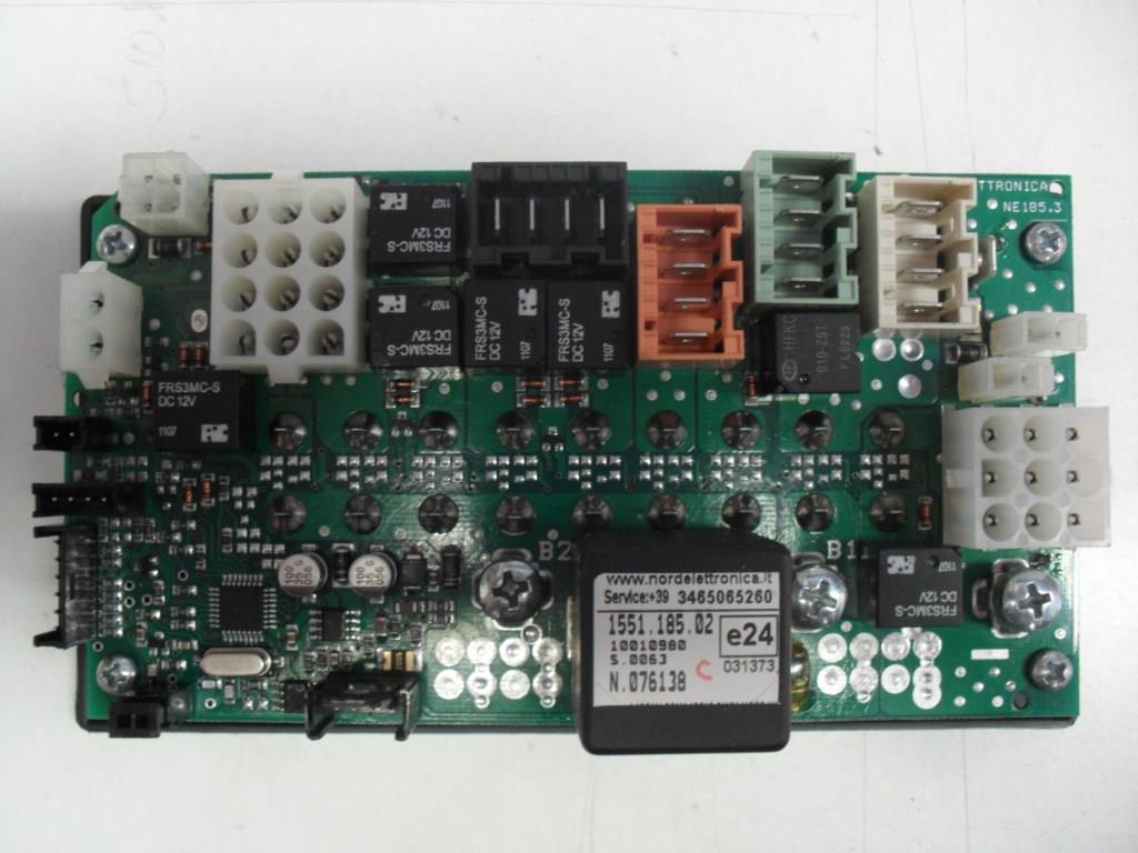
The 'interim' version of these Fuseboards had Stud connectors added, but the manufacturer left the 4 pin sockets in place. Sadly, because it was time consuming to alter the wiring to switch to the Studs, many Technicians didn't bother when they retro fitted a new Fuse board.
On the latest releases of the Fuseboards, the 4 pin sockets are no longer fitted at the factory, to enforce use of the Studs for obvious reasons.
The photo below of an old (interim version with both 4 pin sockets and studs) and new Nordelettronica NE185TR1 side by side.
Tribute PVC
If you are replacing one of these Fuseboards mounted in the side of a seat base on a Tribute PVC just to the rear of the Gear lever, can we suggest you insulate the seat frame legs in the area of the Fuseboard, as 5 of these we have replaced had all failed due to the Fuseboard shorting out on the metal seat 'legs' because space is so tight. The cable protecting 'sleeve' you can buy does a good, neat job of this.
Cable tie the 'sleeve' under the Seat Plastic side cover and it won't show hopefully preventing any further 'shorts'.
CALIRA
The Calira charger units also have the Split charge relay inside the box, so the same limitations apply. While the charger inside the Calira below will take 2 x 80Ah Gel batteries, any prolonged significant current passing through the unit via the far right hand Starter battery and Habitation connector will result in a burn out.
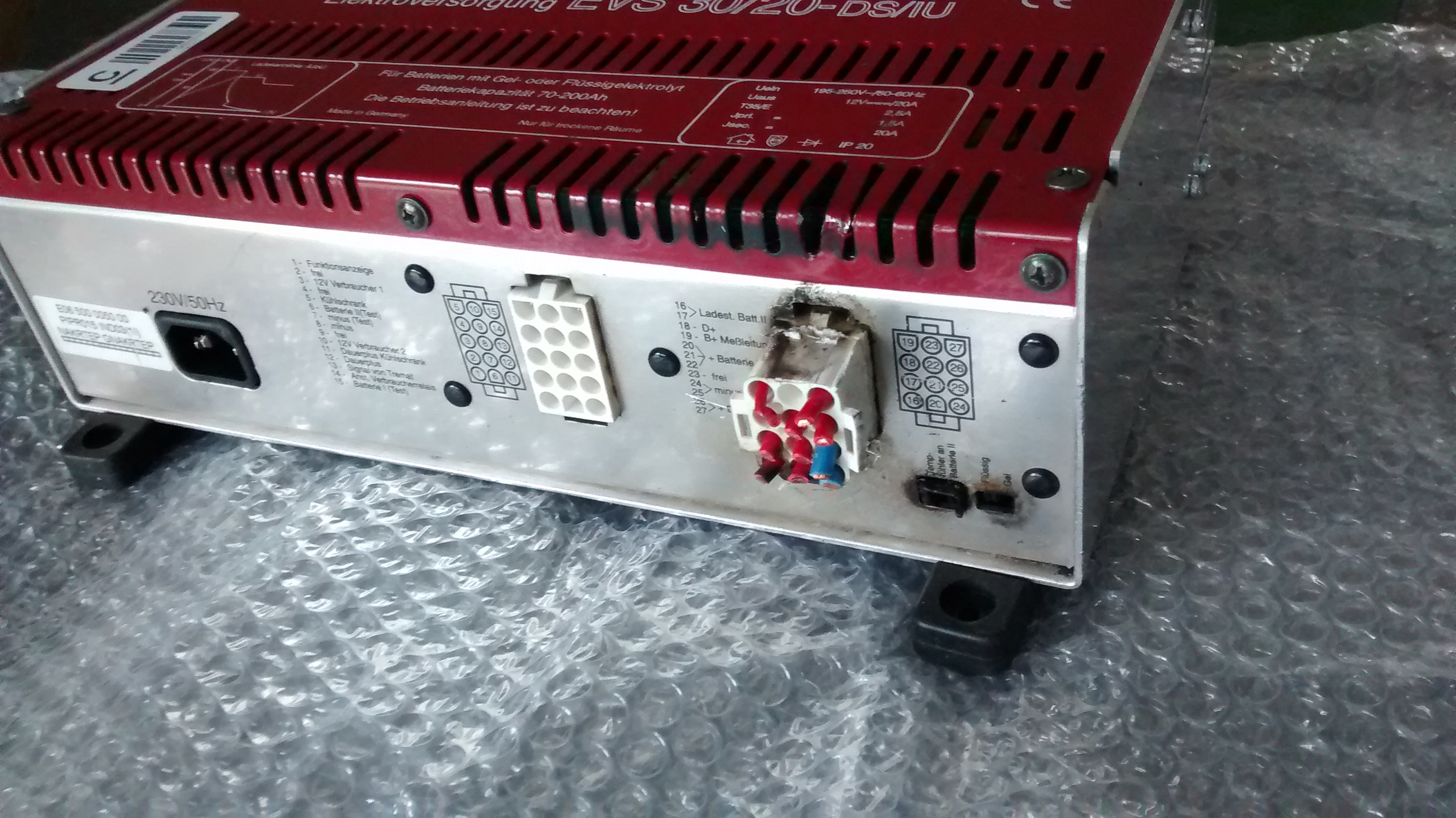
As can be seen from the blackening of the vents above the plug, the internal fire has caused a lot more damage inside than is visible on the outside. The Plug was melted into the socket which was really badly burnt on the two Starter Battery connectors (Alternator feed) to the PCB. The PCB was destroyed and the entire box scrap.

These MNL connectors are rated at about 20amps max, this website below describes them as having a 19a rating :
To avoid issues on the Calira, the Battery bank should be less than 200Ah total size (including the Starter battery which the box also charges) and made up of quality, young and perfect batteries. Don't let the batteries get very low, or tired.
The Calira's are no longer available new, once burnt, you will find yourself between a rock and a hard place.
Take extra care to look after both the Calira 38/20 and the 30/20. Try and ensure it has only the lightest load with two young, high quality batteries of no more than 80Ah each.
Whatever you do replace the batteries, before they get tired. A tiring battery can draw a lot more current.
Schaudt Elektroblock EBL 104 - 106.
The Schaudt EBL 104, like other units above, has the Alternator/Starter battery feed going in through Block C (third MNL connector block from the left) and back out to the Habitation batteries through the same Block.
As per the Calira above the connectors are rated around 20 amps.
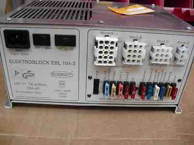
So all charge on the Elektroblock (plus 13amp power for the Fridge) goes in through fairly low rated connectors which can get overloaded if a large battery bank is fitted and/or the batteries are allowed to deteriorate.
Note also that the built in mains charger is very low power, just 10amps, that is a second indicator that it was designed to support no more than a single 100Ah battery.
Thirdly, the cabling thickness also reflects the fact that, like most Motorhomes of the era, they were only expected to have a single battery from the Factory.
These units are particularly vulnerable to damage from an overlarge battery bank.
This 'weakness' was recognised by Schaudt back in 1998 when the introduced the more modern EBL 99 with much more capable, 50amp +, wiring and connectors which were relocated to the rear of the Units.
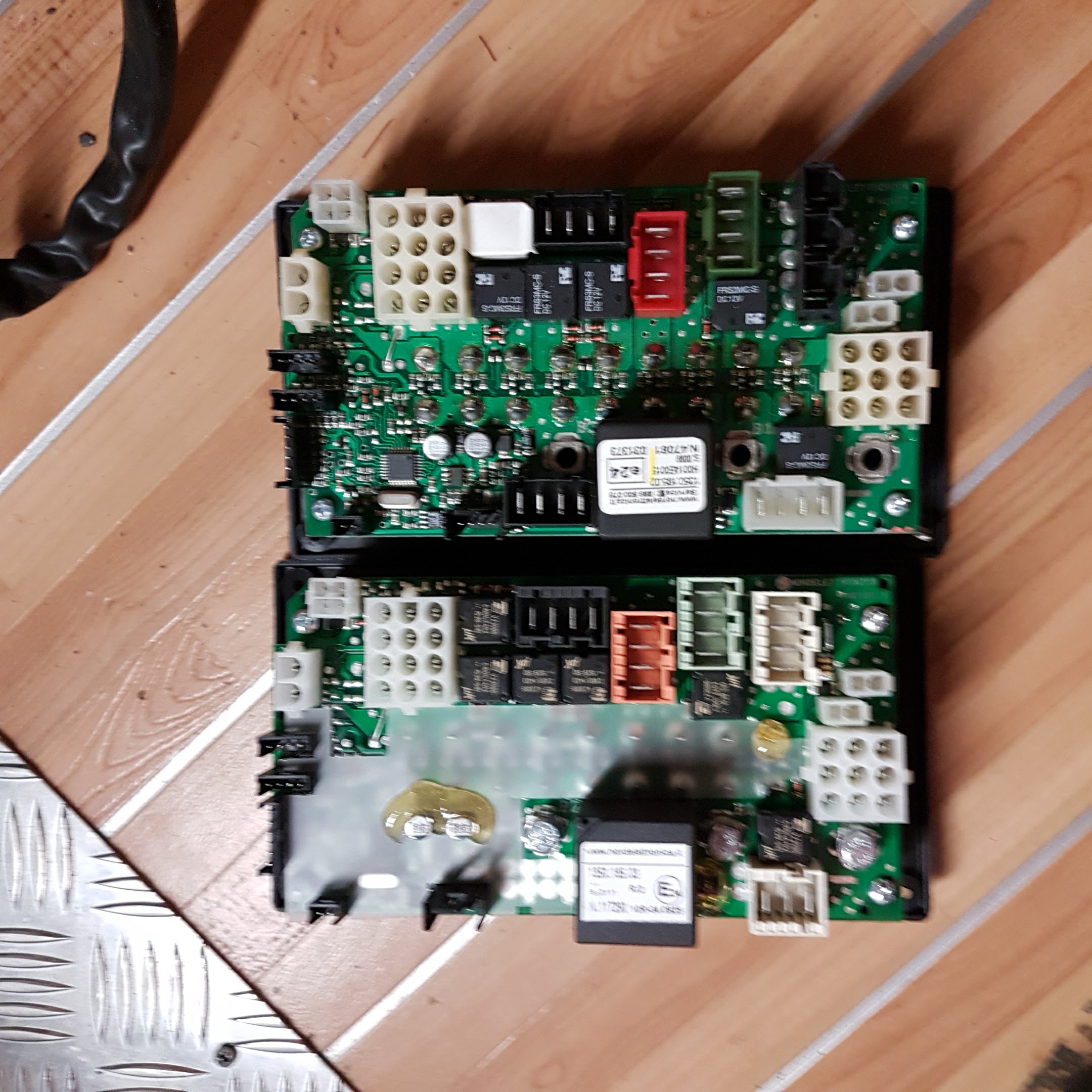
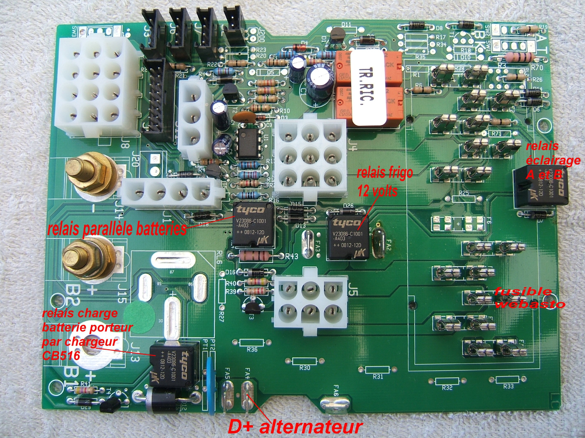
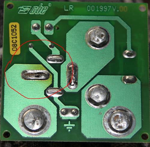
CBE
We don't know much about the CBE DS power unit from the PC100 range but it has good quality Stud connectors and generally, quality cable, but the Split charge relay built into the distribution board, doesn't appear to be expected to handle anything but a low Alternator charge rate.
See example photo below from what is labelled on the web as an early PC100 system. Later systems seem to have a bigger, separate relay.
The very small Tyco split charge relay is identified in the photo by the tag "relais Parallele batteries".
Maybe adequate for a single 100Ah battery in good condition, but it will be severely stretched supplying the Alternator current for 2 x 100Ah batteries that are past their best.
Compare it's size to that of the 'Giant' Nordelettronica relay that still caught fire above.
Remember the size of the relay is not just about the current it can pass safely, but the Voltage drop that is generated on a relay with a small contact area. Burning of relay contacts after a short time in use, may lead to some voltage drop and reduced charge rate.
On a later version of the CBE DS xxx this relay has been uprated, and some are part of a Boite Securite Ralais set-up but even then there have been reports of overheating and failure.
This picture below shows a failing Solder Joint, the design of which isn't one we would expect to reliably carry 50+ amps.
The above examples, from 5 different major Motorhome Electronics manufacturers, shows this isn't just something that affects the odd unit.
We are seeing more units overloaded by poor advice to add batteries without any proviso on whether the unit is capable of handling that load.
Remember also that a big Inverter connected to the Habitation battery may try and draw up to 150 amps from the Alternator if you run the engine while it is operating, assuming it is a high power Alternator.
For one of the above listed units, that might be 150amps going from the Alternator/Starter battery, in through those connectors, then through the internal Split charge relay, around the circuit board before going to the Inverter connected to the Habitation battery.
Some British built Motorhomes may have a separate Split Charge relay mounted outside the main Power Controller/charger unit.
Please be aware that they are not heavy duty items, they will still be subject to overheating/burning if you ask them to look after a bigger battery bank that they were designed to handle, see text below.
Note also that the cabling to the Habitation batteries is woefully undersized compared to French, German, Italian, etc built Motorhomes. Not just inadequate for heavy Alternator charge currents, but also efficiency.
Just because you can safely add additional batteries to some vehicles, doesn't mean you can safely do so to all Motorhomes/Caravans.
If you understand the load you are imposing on the wiring, charger, power distribution unit, Alternator, etc. and then manage it accordingly, then you may be able to work around these limitations.
Things You Might Want to Think About If Increasing The Battery Bank Size, Even Slightly?
Where a Motorhome has separate Split Charge, Fridge, etc Relays, can we suggest you check that the Split Charge relay is of adequate rating if you increase the battery bank size?
While some are 'OK' as far as the 'current rating' goes in passing the extra power from the Alternator to the bigger Habitation battery bank, it is often a good idea to uprate the 'Split Charge' Relay to a higher amperage. This allows you to take advantage of the lower voltage drop that bigger Relay switch contacts should give, especially after a few months use where burning may degrade a smaller relays contacts.
Something like this 100A Relay below found on eBay for less than £9. 200amp for about £12.
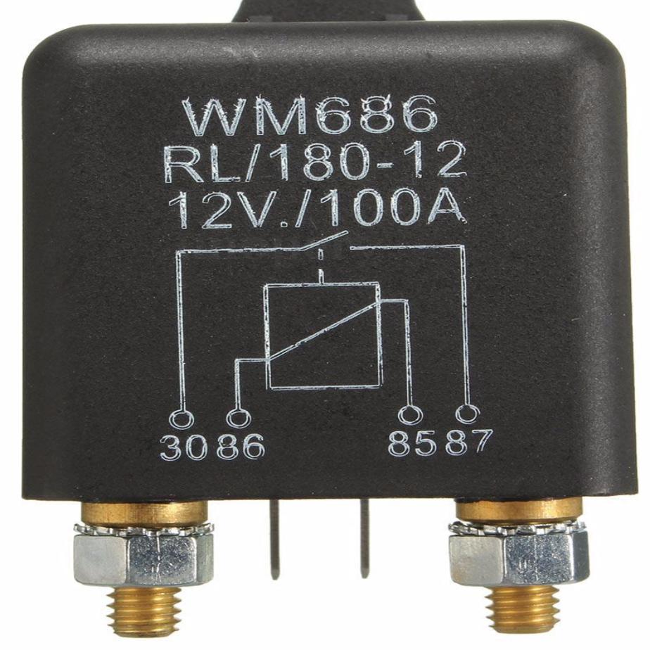
Like the above relay, the best extra heavy duty relays also often have 'bolt on' connectors overcoming the limitations of the Spade type when currents increase. We sometimes see burnt Spade connectors on 'separate relay' installations when batteries are used beyond their life or the bank is increased.
One way of installing a heavy duty relay is to use the output from the existing/old Split charge relay to drive the uprated relay. This prevents the bigger relays coils, which usually draw more current, in the new relay from overloading the low current Alternator D+ circuit.
Don't drive the big heavy Duty relay direct from the D+ circuit unless you are sure the relay coils won't draw more than 0.5 amps max.
If you get issues with the Ignition Warning light illuminating after fitting a Big relay, then that is a solid indication the relay has overloaded the circuit.
Along with decent sized cable, a chunky relay can make quite a difference to the charging rate when Alternator charging on these vehicles. Especially relevant when extra charge current is being passed.
But before you do anything check the impact the Fridge has on the voltage at the habitation battery, if it is significant then starting with the Fridge/Freezer power supply cabling and connections may be a better idea.
Often, fixing a problem with the Fridge draw will also give major benefit to the charging rate as well as improving Fridge efficiency. See further down the web page for a section on the Fridge.
Sometimes the best way of uprating the cable is to run a second parallel cable, rather than ripping out the old and replacing with a single larger cross section cable. Using a single big fat cable can give issues when it comes to connectors, as many readily available connectors won't take very fat cable.
We suggest that DIY solutions are better off utilising two thinner cables, bear in mind that just adding a second cable the same size as the original cable will double the current carrying capability and reduce voltage drop.
However we would suggest a slightly thicker, 10mm, second cable would work even better.
Uprated 50amp/6mm cable is available here for just £1.69 a metre :
So using this cable and a £6 relay from eBay you can supercharge your Swift motorhome Alternator charging for less than £20.
But even better would be this 10mm/70A cable at £2.57/m can be found here : https://www.12voltplanet.co.uk/single-core-thin-wall-cable-10mm2-70a.html
It might be worth thinking about running a separate chunky Negative/Earth cable directly from the Starter battery negative Post to the Habitation Negative battery post on a British built Motorhome, even if you don't uprate the Positive cable.
Even better would be to also run the Negative/Earth lead from the Alternator body to the habitation battery.
Don't trust the Base vehicles Earth to be perfect, especially on a Fiat, Peugeot or Transit Base, as the Engine 'Earths' are known to be a weak point.
If you suffer Alternator failure, quite common on Motorhomes with enlarged battery banks or Lithium upgrades, then take the opportunity of the Garage working in that area to attach a decent sized (minimum 16mm/110amp?) Earth cable from the Alternator body/Lug to the Starter battery negative.
A second Alternator Positive feed would also never hurt, and obviously it would become an essential item if the Alternator has been uprated.
Also think about asking for new Engine/gearbox earth straps.
Uprating the relay and both cables can be as good as installing a B2B.
The aim should be to get the habitation battery voltage to within 0.1v of the voltage at the Starter battery when the Alternator is spinning in order to ensure the enlarged battery bank gets the best possible Alternator charge.
Clearly, if the voltage at the Habitation battery is already the exact same 14.4v of the Starter battery when under Alternator charging and Fridge 14.4v load, then you already have a perfect set-up and don't need to uprate anything.
Poor cabling, connectors or relays between the Alternator and the habitation battery bank will not only reduce the real world charge to the Habitation batteries, extending charge time, but also place extra strain on the Alternator.
Remember the Earth Points focused on here are that of the Alternator, not just Engine or Chassis.
You might have a fantastic Gearbox earth point but if the mounting between the Alternator body and the Engine Block isn't good, you will have problems.
When a modern Motorhome Alternator can pass up to 220amps, it should have it's own dedicated Earth strap to the vehicle body and then onto the Starter Battery.
If you have a Battery To Battery charger or a big battery bank, the Alternator Earth may be critical to reliability and usability. While the B2B instructions might say to take connection points from the Starter battery, it is obviously more sensible to go direct to the Alternator for both Positive and Negative, where appropriate, as this is where the mega amps will come from. Same applies to the feed for a big Split charge relay.
Fridge/Freezer.
Sometimes it is the extra load imposed by the up to 19 amps of a Freezer/Fridge that will take an already poor charging voltage further into the Doldrums. So fixing a poor Fridge wiring set-up first can also pay major dividends with Alternator charge rates.
If you suffer significant voltage drop to the Fridge, the Fridge will obviously be less effective as well as impacting charging.
Some vehicles take the Fridge/Freezer feed from the habitation battery terminals (via Fusing and usual D+ switching) when the best cable run will be from the Alternator.
Some converters wire the Fridge from the Starter battery (via Fusing and D+ switching) which is a much better option than using the habitation battery, but still not as good as an Alternator option.
While the advantages of these different 'start' points for the wiring may not be an immediately obvious cause for voltage drop at the habitation battery, we have seen a better than 1.0 volt improvement in habitation battery charging just by moving the Fridge feed from the habitation battery terminals to the Starter battery terminal.
We were surprised to see just how much the charge current also went up with the improved voltage from rewiring the Fridge. One owner reported that the charge times were 'slashed by half', but that was a subjective comment.
If the original Fridge feed comes from the habitation battery, find the Fridge D+ operation circuit in the Power Controller/Fuse unit and use it to operate a new big relay that takes it's feed directly from the Alternator B+ post and a big Fat Earth from the Alternator body mounting.
Not only will the Fridge be more efficient but the Habitation battery charge voltage will rise significantly.
I think you will be surprised by the results that just basic, easy cable changes can make.
Suggestions on how to check the effectiveness of various Earth points.
This is not an idiots guide, you need to understand the basics.
Turn EHU 'OFF' and isolate the Solar Panel, if fitted.
Then get a pen and paper to record the readings we will take.
Discharge the batteries slightly so the Alternator actually has some charging to do.
With the engine running at a fast idle/1,500 rpm :
With the Fridge 'OFF 12v' (either off altogether or manually set to Gas and no 'consumers' active, record the voltage readings at the Starter battery Posts.
It should be 14.4v on a none Brake energy recuperation or Stop/Start vehicle.
If it is any less than this than something may be amiss with the Alternator or Earth points..
If the reading is low, consider repeating the voltage checks using a 'Black/negative Jump Lead' to create a temporary Earth strap clamped between the Alternator body to Chassis.
Always to perfect shiny metal, it is really important that the Jump Lead has absolutely perfect connectivity as the slightest poor connection will skew the results.
Record the voltage.
Then repeat with the Black Jump Lead running from the Starter battery Negative terminal and the Alternator earthed body or as close to it as you can get on the Engine.
On a Motorhome with the Starter battery under the Cab floor or Seat where a standard Jump Lead may not be long enough, just Clamp the Black Jump lead between the Starter battery Negative terminal and the Chassis.
Compare voltages and see where the Black jump lead made a difference and fit a strap at that logical point, if needed.
What we are primarily comparing here is not just the Starter Motor Earth functionality, but the effectiveness of the Alternator Earthing.

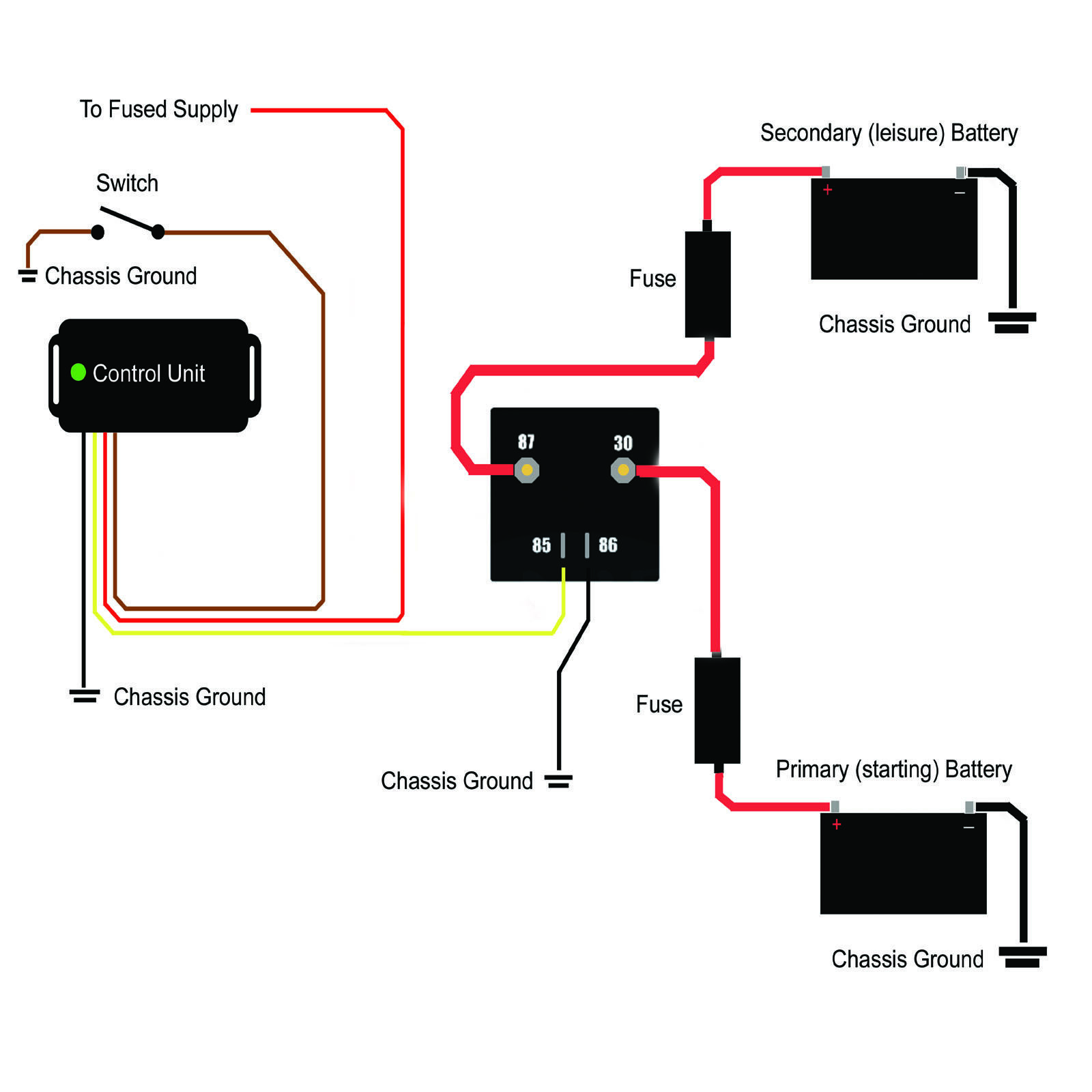
If using a Voltage Sensing Relay then note that most quality batteries these days are 12.8v to 13.0v when most VSR's only disconnected at 12.6 - 12.8v so the will keep the batteries permanently connected.
The unit below is a '2 Part' VSR, a £25 voltage sensing device and a separate relay, which allows you to power the VSR from an Ignition switched supply to drive any ordinary relay.
When the ignition is turned off and the supply cut, the relay opens regardless of the battery voltage.
It must be powered from an Ignition switched supply, not a permanent live supply.
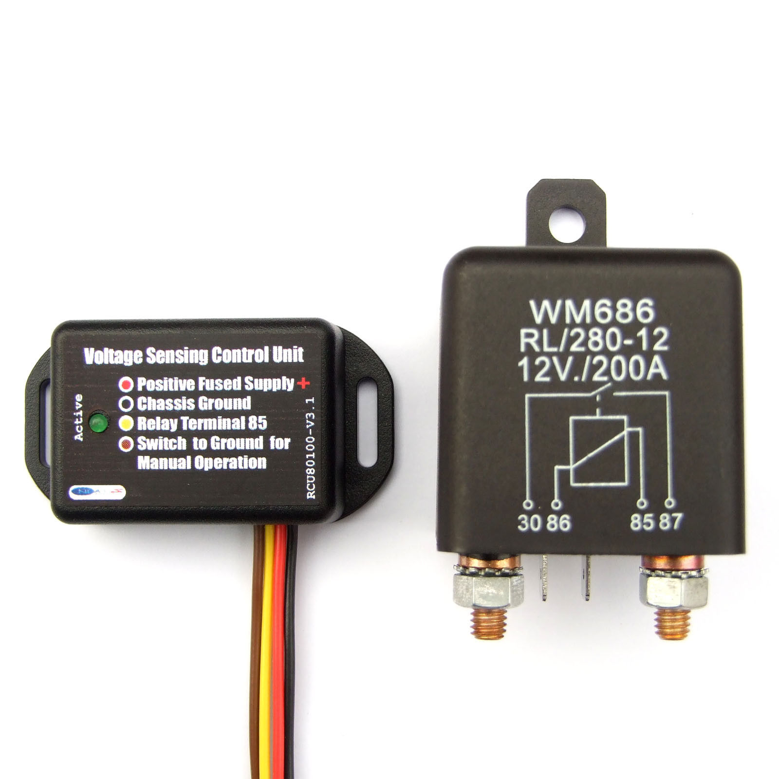
https://www.ebay.co.uk/itm/200-Amp-Split-Charge-Relay-Voltage-Sensing-Control-Unit-With-Manual-Switching/322882862328?_trkparms=aid%3D444000%26algo%3DSOI.DEFAULT%26ao%3D1%26asc%3D20170221122447%26meid%3D7806528f6ba24ab2aa8d8413b7489481%26pid%3D100752%26rk%3D1%26rkt%3D6%26mehot%3Dag%26sd%3D322865585299%26itm%3D322882862328&_trksid=p2047675.c100752.m1982